Localizer
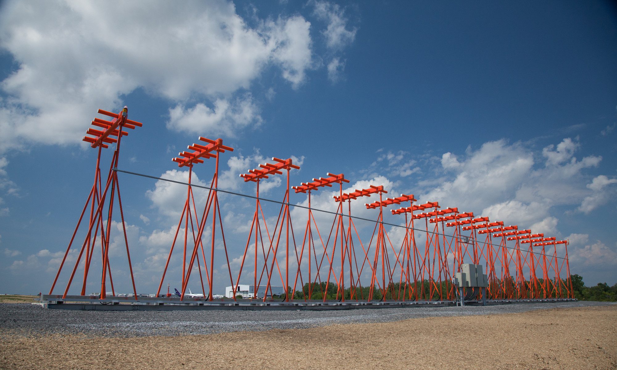
One of the main components of the ILS system is the localizer which handles the guidance in the horizontal plane. The localizer is an antenna system comprised of a VHF transmitter which uses the same frequency range as a VOR transmitter (108,10 ÷ 111,95 MHz), however the frequencies of the localizer are only placed on odd decimals, with a channel separation of 50 kHz. The trasmitter, or antenna, is in the axis of the runway on it’s other end, opposite to the direction of approach. A backcourse localizer is also used on some ILS systems. The backcourse is intended for landing purposes and it’s secured with a 75 MHz marker beacon or a NDB (Non Directional Beacon) located 3÷5 nm (nautical miles), or 5,556÷9,26 km before the beginning of the runway.
The course is periodically checked to ensure that the aircraft lies in the given tolerance
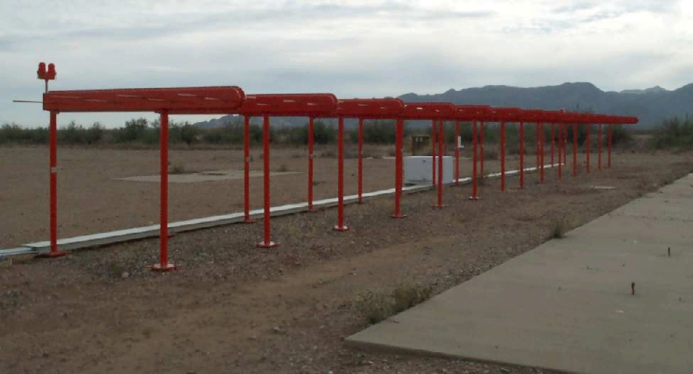 Figure 2 – Antennas of the localizer system
(figure source: http://www.airfields-freeman.com/AZ/Whitman_AZ_localizer_02.jpg)
The transmitted signal:
The localizer, or VHF course marker, emits two directional radiation patterns. One comprises of a bearing amplitude-modulated wave with a harmonic signal frequency of 150 Hz and the other one with the same bearing amplitude-modulated wave with a harmonic signal frequency of 90 Hz. These two directional radiation patterns do intersect and thus create a course plane, or a horizontal axis of approach, which basically represents an elongation of the runway’s axis (see Fig. 3).
For an observer – a pilot, who is situated on the “approaching” side of the runway (therefore in front of the LLZ antenna system) predominates a modulation of 150 Hz on the right side of the course plane and 90 Hz on the left. The intersection of these two regions determines the on-track signal.
The width of the navigational ray can span from 3° to 6°, however mostly 5° are used. The ray is set to secure a signal approximately 700 ft (213, 36 m) wide on the borderline of the runway. The width of the ray magnifies, so at a distance of 10 nm (18,52 km) from the transmitter is the ray about 1 nm (1,852 km) wide.
The range of the localizer can be even 18 nm (33,336 km) in the 10° field from the center of the ray (on-track signal) and 10 nm (18,52km) in the field 10°÷35° from the center of the ray, because the main part of the signal is coaxial with the middle of the runway. The localizer is identified by an audio signal added to the navigational signal. The audio signal consists of letter „I“, following with a two-letter addition, for example: „I-OW“.
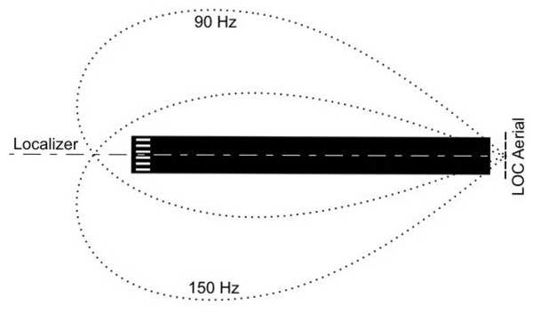 Figure 3 – Radiation pattern of the localizer’s VHF transmitter
(figure source: http://en.wikipedia.org/wiki/File:ILS_illustration.jpg)
UHF descent beacon – glide slope
The transmitted signal:
The glide slope, or angle of the descent plane provides the vertical guidance for the pilot during an approach. It’s created by a ground UHF transmitter containing an antenna system operating in the range of 329,30÷335.00 MHz, with a channel separation of 50 kHz.
The transmitter (Fig. 4) is located 750÷1250 ft (228,6÷381 m) from the beginning of the runway and 400÷600 ft (121,92÷182,88 m) from it’s axis. The observed tolerance is ±0,5°. The UHF glide slope is „paired“ with the corresponding frequency of the VHF localizer.
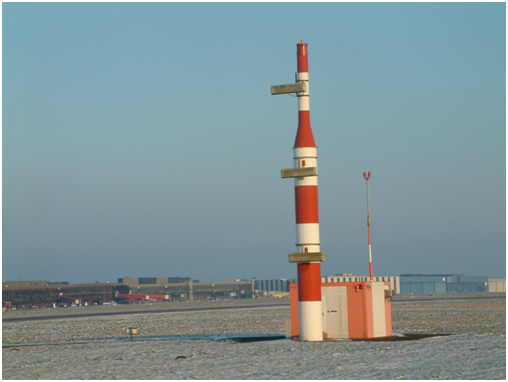 Figure 4 – The UHF descent beacon draws a glide slope in the area
(figure source: http://upload.wikimedia.org/wikipedia/commons/6/6f/EDDV-ILS_09R_Glideslope.jpg)
Like the signal of the localizer, so does the signal of the glide slope consist of two intersected radiation patterns, modulated at 90 and 150 Hz. However unlike the localizer, these signals are arranged on top of each other and emitted along the path of approach, as you can see in Fig. 5. The thickness of the overlaping field is 0,7° over as well as under the optimal glide slope.
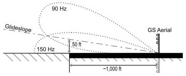 Figure 5 – The radiation pattern of the UKV descent beacon forming the glide slope
(figure source: http://en.wikipedia.org/wiki/File:ILS_illustration.jpg)
The signal of the glide slope can be set in the range of 2°÷4,5° over the horizontal plane of approach. Typically it’s a value of 2,5°÷3°, depending of the obstacles along the corridor of approach and the runway’s inclination.
False signals can be generated along the glide slope. It’s happening in multiples of the angle that‘s formed by the glide slope and the horizontal plane. The first case arises at approximately 6° over the horizontal plane. These false signals are inversive, which means that the directions to climb or descend will be swapped. A false signal at 9° will be oriented the same as the real glide slope. There are no false signals under the glide slope.
