Categories of operation minimums.
Category I
- A minimal height of resolution at 200 ft (60,96 m), whereas the decision height represents an altitude at which the pilot decides upon the visual contact with the runway if he’ll either finish the landing maneuver, or he’ll abort and repeat it.
- The visibility of the runway is at the minimum 1800 ft (548,64 m)
- The plane has to be equipped apart from the devices for flying in IFR (Instrument Flight Rules) conditions also with the ILS system and a marker beacon receiver.
Category II
- A minimal decision height at 100 ft (30,48 m)
- The visibility of the runway is at the minimum 1200 ft (365,76 m)
- The plane has to be equipped with a radio altimeter or an inner marker receiver, an autopilot link, a raindrops remover and also a system for the automatic draught control of the engine can be required. The crew consists of two pilots.
Category III A
- A minimal decision height lower than 100 ft (30,48 m)
- The visibility of the runway is at the minimum 700 ft (213,36 m)
- The aircraft has to be equipped with an autopilot with a passive malfunction monitor or a HUD (Head-up display).
Category III B
- A minimal decision height lower than 50 ft (15,24 m)
- The visibility of the runway is at the minimum 150 ft (45,72 m)
- A device for alteration of a rolling speed to travel speed.
Category III C
- Zero visibility
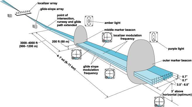
Basic elements of the ILS system and THEIR brief description
The ILS system consists of four subsystems:
- VHF localizer transmitter
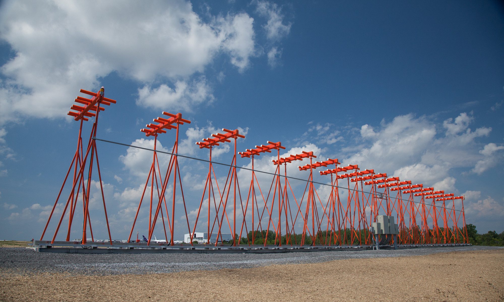
- UHF glide slope transmitter
- marker beacons
- approach lighting system

Figure 1 – The description and placement of the individual parts of the ILS system
(figure source: http://niquette.com/books/chapsky/skypix/ILS.gif)
