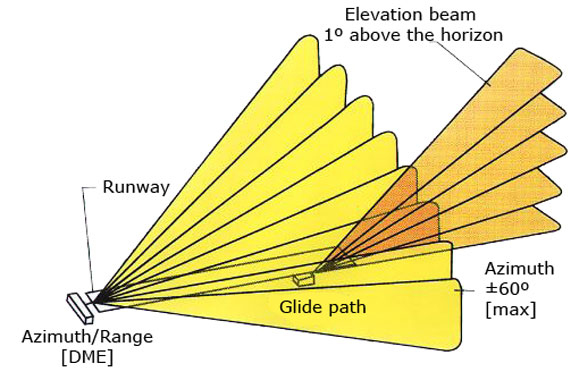
The MLS system is comprised of ground pieces of equipment that are divided into the protractor components, rangefinder components, and the onboard hardware. The information about the angles of the approach course, descent, flare and the course of an unsuccessful approach are aquired through an onboard antenna or the aircraft itself by measuring the time between two passages of an oscillating lobe of a high frequency signal . The distance is determined with the help of an ancillary device, the DME rangefinder. The MLS system further sends with the help of phase modulation and time-division multiplexing additional data, as identification, system status and so on. The ground equipment consists in the basic configuration of an Azimuth Transmitter (AZ) with an added DME rangefinder, perhaps even a more precise DME/P, in close distance of a course transmitter and near an elevation transmitter, see Fig. 1. A scaled up configuration is supplemented with a course transmitter for an unsuccessful approach and a flare transmitter.
 Figure 1 – A display of the MLS components and their approximate placement beside the runway.
(figure source: http://oea.larc.nasa.gov/trailblazer/SP-4216/photos/p42a.JPG)
Ground Distance Measuring Equipment (DME)
The rangefinder unit presents a DME which is positioned together with the course transmitter. In connection with requirements of accuracy of the MLS system arose a demand to refine the DME system, which was accomplished with the accurate DME/P rangefinder (along with the DME/W and DME/N). Hence the function of the DME is to provide a pilot information about the distance from a specific point which is essential for pinpoint calculation of the plane’s position in the three-dimensional space.
Ground protractor components
The ground principle of both protractor parts of the MLS system for horizontal and vertical homing of an aircraft is to create levelled emiting diagrams, oscillating at a constant speed in directions „TO‘‘ and „FROM“, and to measure the elapsed time between two passages of an oscillating plane lobe through an onboard MLS antenna.
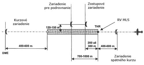
 Figure 2 – Scheme of a ground protractor set-up of the MLS system.
A runway fully equipped with the MLS system contains four transmitters. Two relays supply information about the angle of the azimuth (horizontal) plane and are located face to the runway, along it‘s axis. They are appended with a DME or DME/P rangefinder device, while one of the transmitters is dessignated for the course of approach and the other for the course of an unsuccessful approach. They are positioned 400-600 m from the runway’s threshold. Another two relays transmit angular information for the descent and flare (taking over the function of a descent beacon in the ILS). These are located at a distance of 120-150 m from the runway’s axis, while the transmitter of descent signals is situated 200-300 m from the runway’s threshold and the flare relay 700-1000 m from the beggining of the runway in the direction of approach. If the runway’s equipped with both azimuthal relays, then the relay whose antenna is turned in the direction of an approaching aircraft (the transmitter on the faraway side of the runway) represents an approach course transmitter and the relay close to the approaching aircraft takes over the function of an unsuccessful course transmitter. It’s similar also for the descent and flare relays.
