Localizer receiver
The signal is received on board of an aircraft by an onboard localizer receiver. A simplified block scheme of the onboard receiver of the localizer’s signals is displayed in Fig. 6. The localizer receiver and the VOR receiver form a single unit. The signal of the localizer launches the vertical indicator called the track bar (TB). Provided that the final approach does occur from south to north, an aircraft flying westward from the runway’s axis (Fig. 7) is situated in an area modulated at 90 Hz, therefore the track bar is deflected to the right side.
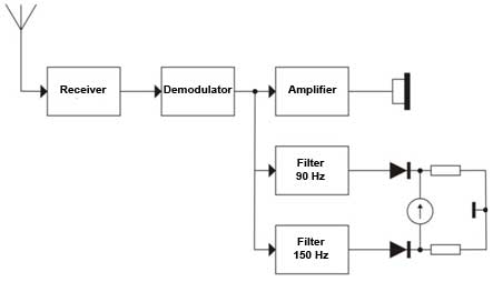 Figure 6 – Block scheme of the onboard course beacon‘s signal receiver
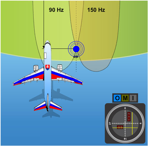 Figure 7 – A plane flying approximately along the axis of approach, however partially turned away to the left
On the contrary, if the plane’s positioned east from the runway’s axis, the 150 Hz modulated signal causes the track bar to lean out to the right side. In the area of intersection, both signals affect the track bar, which causes to a certain extent a deflection in the direction of the stronger signal. Thus if an aircraft flies roughly in the axis of approach leaned out partially to the right, the track bar is going to deflect a bit to the left. This indicates a necessary correction to the left. In the point where both signals 90 Hz and 150 Hz have the same intensity, the track bar is in the middle. Meaning that the plane is located exactly in the approach axis (Fig. 9).
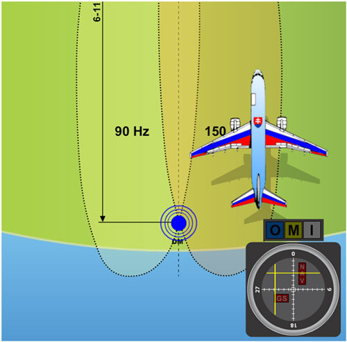 Figure 8 – A plane flying nearly in the approach axis slighlty leaned out to the right
When the track bar is used in conjunction with a VOR, a lean out of 10° to one or the other side from the signal causes a full deflection of the indicator. If the same pointer is used as an indicator of the ILS localizer, a full deflection will be induced by a 2,5° diversion from the center of the localizer’s beam. Therefore the sensitivity of the TB is roughly four times greater in the function as an indicator of the localizer as at the indication of information from the VOR.
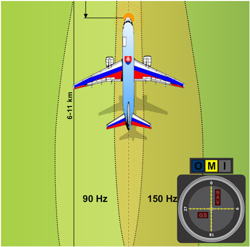 Figure 9 – A plane flying exactly in the axis of approach
In case that a red NAV bat appears in the upper right section of the onboard ILS indicator (Fig. 10), it represents that the signal is far too weak or out of the receiver’s reach and for that reason the pointer’s deflection cannot be considered to be accurate. The vertical pointer will return to the neutral position, meaning to the center of the indicator. A momentary display of the NAV bat, short deviations of the TB, or both instances happening at once can occur in the case that an aircraft flies between the receiver’s antenna and the transmitter, or some other obstacle gets into their way.
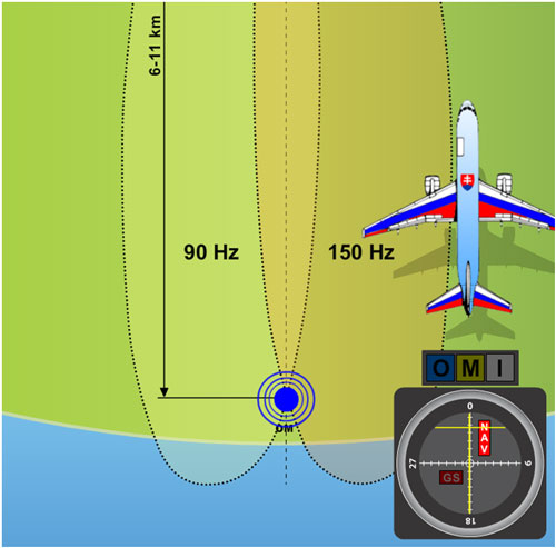 Figure 10 – A plane situated out of reach of the VKV course beacon’s signal
glide slope receiver
The glide slope’s signal is on board of a plane received by means of a UHF antenna. In modern avionics are the controls for this receiver combined with the VOR’s controls, so the correct frequency of the glide slope beacon is tuned in automatically at the instant when the localizer’s frequency is selected.
The glide slope’s signal puts the horizontal pointer of the glide slope into operation which intersects the TB, see Fig. 13 and Fig. 14. This indicator has its own GS bat which lights up whenever the glide slope beacon’s signal is too weak or the onboard receiver, hence the whole aircraft is out of the signal’s reach (Fig. 11).
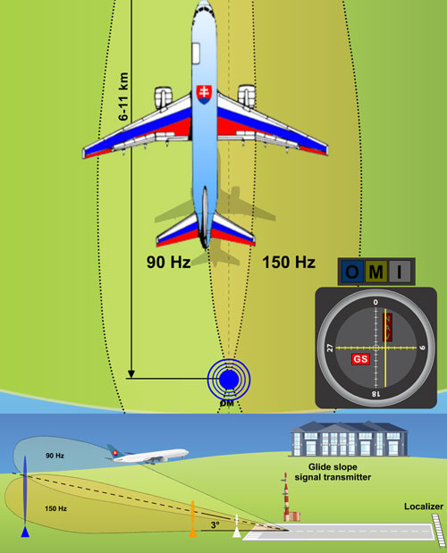 Figure 11 – An example of the displayed GS pointer notifying a diversion from the glide slope, a too weak received signal, or an obstacle on the way.
The onboard indicator of the ILS system can be used by a pilot to determine the exact position because it provides vertical as well as horizontal guiding. The case in Fig. 12 portrays both indicators in the middle, which means that the aircraft is located in the point of intersection of the course plane (horizontal) and the glide slope. The event pictured in Fig. 13 indicates that the pilot must descent and correct the flight course to the left in order to aquire the correct course and glide slope level. The case in Fig. 14 shows a necessity to ascend and adjust the flight course to the right.
With a 1,4° overlapping of the beams is the area around 1500 ft (457,2 m) wide at a distance of 10 NM (18,52 km), 150 ft (45,72 m) at a distance of 1 NM (1,852 km), and less than one foot (0,3 m) at the instant of touch down.
The apparent sensitivity of the instrument increases as the aircraft closes in to the runway. The pilot has to watch the indicator with attention so that he can keep an overlap of both needles of the pointer in the middle of the indicator. Thereby he’ll achieve a precise homing all the way to the touch down.
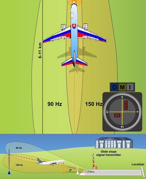 Figure 12 – Both pointers in the middle – the aircraft is located in the point of intersection of the course and descent plane.
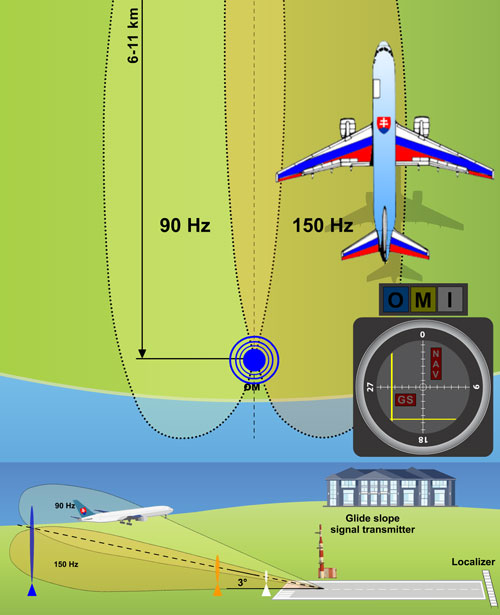 Figure 13 – A case when the aircraft is located right of the runway’s axis and too high over the glide slope.
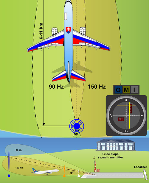 Figure 14 – A case when the aircraft is located left of the runway’s axis and too low under the glide slope.
